A contactor that matches only the motor’s horsepower can fail early, overheat, weld its contacts, or interrupt the wrong type of current. By the end, you will be able to match the switching category, electrical ratings, coil, duty cycle, auxiliary contacts, and upstream protection to the actual application.
Key takeaways
- Choose utilization category before comparing amperage ratings.
- Check motor duty, electrical endurance, ambient temperature, and enclosure conditions.
- Match coil voltage and auxiliary contacts to the control system.
- Coordinate contactor ratings with overload and short-circuit protection.
Start with the Contactor’s Switching Job and Ratings
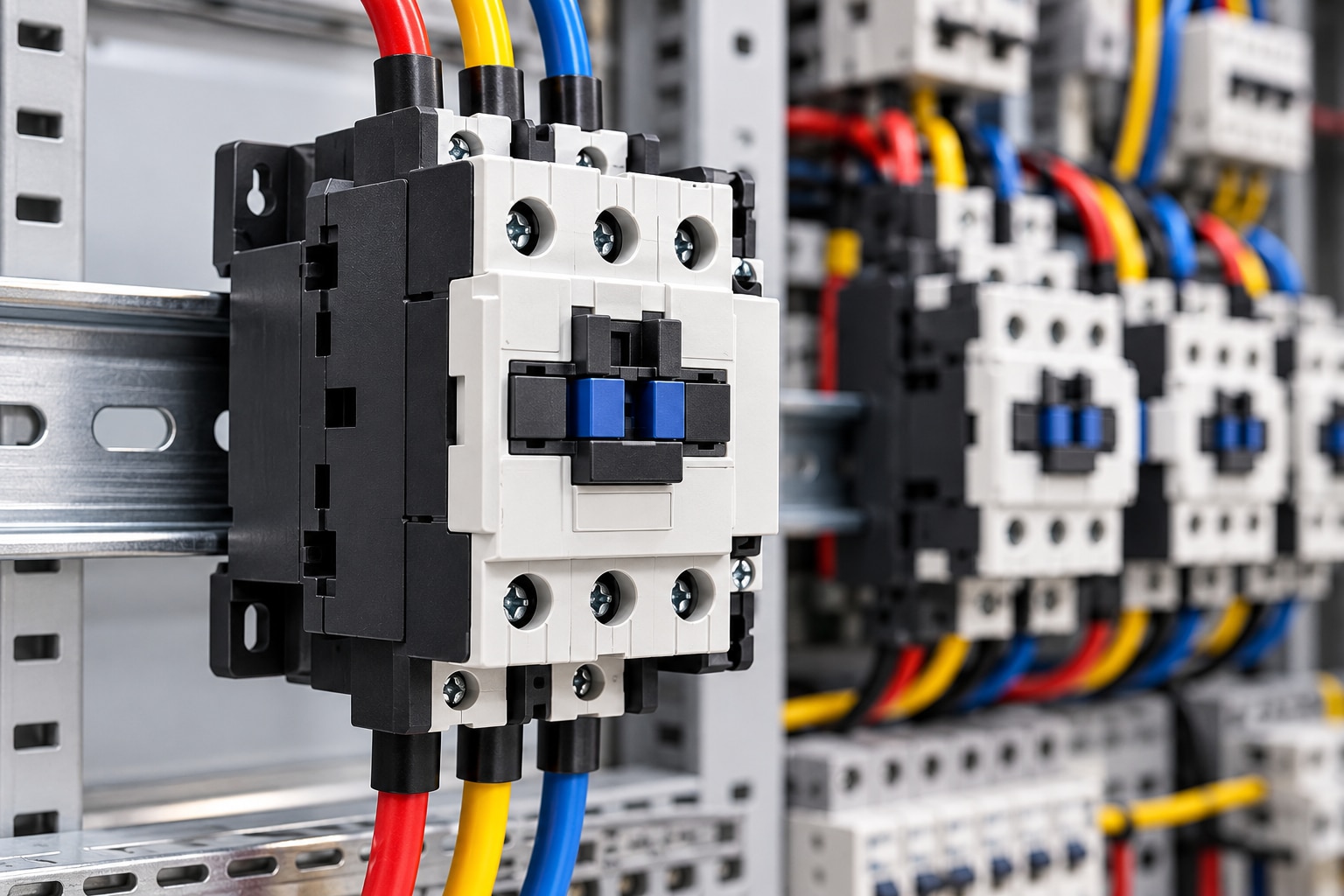
Energizing the contactor coil creates a magnetic field that pulls an armature closed. The main contacts then connect or disconnect the power circuit, while auxiliary contacts report state or operate interlocks in the control circuit.
Arc suppression limits damaging voltage and contact arcing; choose it for the actual AC or DC circuit, because the wrong device can delay release or fail to interrupt safely.
| Rating | What it tells you | Check before selection |
|---|---|---|
| Ie | Rated operational current | Actual voltage, load, utilization category, and duty |
| Ith | Conventional free-air thermal current | Heating limit, not a universal switching rating |
| Ui | Rated insulation voltage | System voltage and insulation coordination |
| Uimp | Rated impulse withstand voltage | Required surge and transient withstand |
| Short-circuit data | Conditional withstand with specified protection | Fuse or breaker type, rating, and coordination |
For a squirrel-cage motor, AC-3 covers starting and stopping at running speed; AC-4 covers inching, plugging, and frequent starts, where interruption occurs during acceleration. AC-1 suits predominantly resistive loads, while AC-6b applies to capacitor switching where specified.
Do not interchange AC and DC ratings: DC has no natural current zero, so verify voltage, current, polarity, time constant, or stored inductive energy. Check electrical endurance and operations per hour, not mechanical endurance alone.
Select auxiliary contacts by their own utilization category and current; a PLC input, relay coil, and transformer primary impose different duties.
Choose the Utilization Category Before Comparing Current Ratings
A 22 A motor does not automatically need a 22 A contactor. Select the utilization category from the switching duty, then check rated operational current Ie at the actual voltage, phase arrangement, load type, duty cycle, and switching frequency. Ith is a conventional free-air thermal limit, not a universal switching rating.
| Category | Load and switching duty | Current-selection rule |
|---|---|---|
| AC-1 | Predominantly resistive loads, such as heaters | Match Ie to the steady load current at the stated voltage |
| AC-3 | Squirrel-cage motor starting and stopping | Match Ie to the motor’s full-load current and verify the motor voltage and kW |
| AC-4 | Inching, jogging, plugging, or frequent reversal | Use the manufacturer’s AC-4 Ie; an AC-3 rating is not enough |
| AC-6b | Capacitor switching, where the contactor is explicitly rated for it | Check capacitor-duty Ie and inrush limits; do not substitute a standard motor contactor |
Transformer primaries and capacitor banks produce transients that steady-state amperes hide. Require a rating for magnetizing or capacitor inrush, and use inrush-limiting equipment when specified.
For DC, use the stated DC breaking rating at maximum voltage, current, time constant, and polarity. AC and DC ratings cannot be exchanged. For photovoltaic or battery circuits, verify continuous and breaking ratings at maximum open-circuit voltage and prospective fault current; follow any required pole polarity or series-pole wiring.
Size auxiliary contacts separately. Check their own utilization category and current for a PLC input, relay coil, or transformer primary.
Account for Motor Duty, Endurance, and Installation Conditions
An AC-3 contactor is not automatically suitable for every motor starter. Direct-on-line starting and normal stopping switch a squirrel-cage motor after it reaches speed; reversing, jogging, and plugging interrupt high motor current during acceleration, increasing contact wear and demanding AC-4-rated performance.
| Duty | Selection consequence | Failure risk |
|---|---|---|
| Direct-on-line starting | Use the AC-3 Ie rating at the motor voltage and full-load current | Undersizing shortens contact life during starting |
| Reversing, jogging, or plugging | Select for AC-4 duty and the stated cycles per hour | Contacts can weld or erode rapidly |
| Transformer or capacitor switching | Use equipment rated for its inrush duty, not a motor contactor chosen by amperes alone | Transient current can damage contacts |
Compare electrical endurance with your required operations per hour and total service life. Mechanical endurance is measured with little or no load; it does not prove the contactor will survive motor switching.
- Record starts, reversals, jogs, and plugs per hour; excessive frequency can cause contact bounce, coil overheating, or insufficient cooling time.
- Check the manufacturer’s ambient-temperature range, altitude limit, enclosure IP rating, dust, moisture, and vibration requirements.
- Allow for derating when the enclosure traps heat or the installation exceeds the stated conditions.
- Select a device whose electrical endurance matches the planned life, not one advertised only with a large mechanical-operation figure.
Match the Coil and Auxiliary Contacts to the Control System
Start with the PLC output and verify that it can drive the contactor’s coil, not merely that the labels show the same control voltage. Match the AC or DC coil waveform exactly; a 24 V AC coil is not interchangeable with a 24 V DC coil.
- Confirm the coil’s permissible voltage tolerance, pickup voltage, dropout voltage, inrush current, and sealed coil consumption. Compare the output module’s sourcing or sinking capacity with both the pickup demand and continuous holding demand.
- Check suppression. A DC suppression diode needs correct polarity and can lengthen dropout, delaying motor release or interlocking.
- Select auxiliary contacts by their own utilization category and current at the circuit voltage. A PLC feedback input, inductive relay coil, and control-transformer primary impose different duties.
- Verify the normally open and normally closed contact ratings separately, including any permitted combination of contacts. Do not assume an auxiliary contact carries the main-pole rating.
For battery or photovoltaic control, check the contactor’s DC breaking rating at maximum open-circuit voltage and prospective current. Follow stated polarity and series-pole wiring instructions; terminal count alone does not establish the rating. Test the PLC input’s expected feedback voltage and leakage current against the auxiliary contact circuit.
Coordinate Short-Circuit and Overload Protection
A contactor does not clear a short circuit. Pair it with an overload relay for sustained overcurrent and an upstream fuse, MCCB, or motor circuit breaker for fault interruption.
Select the overload relay from the motor’s full-load current and set it to the manufacturer’s permitted range; an incorrect setting can either trip during starting or leave the motor dangerously hot.
The contactor’s short-circuit rating is conditional, not standalone. Confirm the manufacturer’s tested combination, including:
- Protective device type: fuse, MCCB, or motor circuit breaker
- Protective-device current rating and trip characteristics
- Maximum prospective short-circuit current
- Required IEC coordination Type 1 or Type 2, or the UL/CSA combination SCCR
Type 1 permits specified equipment damage after a fault. Type 2 requires the starter to remain suitable for service, with contact welding limited to the conditions tested for that combination. Do not substitute a different breaker or fuse and retain the published rating.
Reversing and star-delta starters need both electrical and mechanical interlocking. Use normally closed auxiliary contacts in each opposing coil circuit, then add a mechanical interlock that prevents both contactors from closing physically. Control logic alone cannot protect against welded contacts, a failed PLC output, or a wiring fault.
Rate auxiliary contacts for their own duty and current. A PLC input, relay coil, and control-transformer primary can require different contact categories and ratings.
Build a Specification That a Supplier Can Verify
Give every supplier the same industrial duty sheet; otherwise one quote may show a continuous-current number while another shows a switching rating. State load voltage, AC or DC, phase count, load type, utilization category, steady current, inrush or fault current, switching frequency, cycles, and required electrical life.
- Identify rated operational current Ie at the actual voltage, category, duty cycle, and load. Do not use conventional free-air thermal current Ith alone; Ith describes heating under specified conditions, not switching capability.
- Request rated insulation voltage Ui and rated impulse withstand voltage Uimp for insulation coordination.
- For photovoltaic or battery circuits, give maximum open-circuit voltage, prospective fault or load current, DC time constant or inductive energy, polarity, and required pole-series arrangement. Verify DC breaking data; AC ratings do not transfer.
- Add ambient and enclosure temperature, altitude, mounting orientation, adjacent heat sources, operations per hour, and lifetime.
- For transformers or capacitor banks, state magnetizing inrush or capacitor duty and inrush-control method.
Yueqing Growmore Electric Co can be compared fairly when you send this schedule and request datasheet values, derating curves, wiring limits, and test conditions rather than a catalogue ampere figure.
Related product
 | Contactors & RCCB Yueqing Growmore Electric Co., Ltd. - Your Trusted Partner in AC Contactors Company Overview Founded in the heart of China's electrical hub, Yueqing... View product → |
Frequently asked questions
How do you choose the correct contactor for an industrial application?
Define the switching job, load type, utilization category, current and voltage ratings, duty cycle, endurance, installation conditions, coil requirements, and auxiliary contacts.
Why is utilization category more important than the contactor’s current rating?
Utilization category reflects how the contactor switches the load. A motor, heater, capacitor bank, and lighting circuit impose different opening and closing stresses even at similar current values.
What coil and auxiliary contact details must you verify?
Verify the coil’s control voltage and AC or DC type, then confirm auxiliary contact arrangement, contact ratings, and the signals required for interlocks or status feedback.
How should a contactor coordinate with overload and short-circuit protection?
Specify the overload relay or motor protection device and the upstream fuse or circuit breaker with the contactor. Check ratings, trip settings, and coordination documentation for the complete assembly.