A photovoltaic fault can keep receiving current from several parallel strings, while a DC arc continues after the conductor has melted. By tracing the fuse’s interruption process, its position in the array, and the ratings shared by the fuse and base, you can evaluate whether a protection assembly is suitable for the circuit rather than choosing by ampere marking alone.
Key takeaways
- Place the fuse in each required PV string conductor before the strings combine.
- Select a PV-rated fuse for the circuit voltage, current, and available fault current.
- Match the fuse base to the fuse size, voltage, polarity, and DC insulation requirements.
- Verify polarity, torque, continuity, and isolation before energizing the array.
How the Fuse Stops a Solar DC Fault
Excessive current through a fuse creates heat in its melting element, with heating rising roughly as current squared. At the designed threshold, the element melts and opens the circuit. That sequence is DC fuse operation.
Photovoltaic current does not pass through a natural zero as AC current does. The resulting gap can sustain an arc, so the fuse must perform DC arc interruption by stretching, cooling, and de-ionizing the arc path inside its body.
If the fuse’s DC voltage or interrupting rating is too low for the prospective fault current, the arc can continue and destroy the fuse.
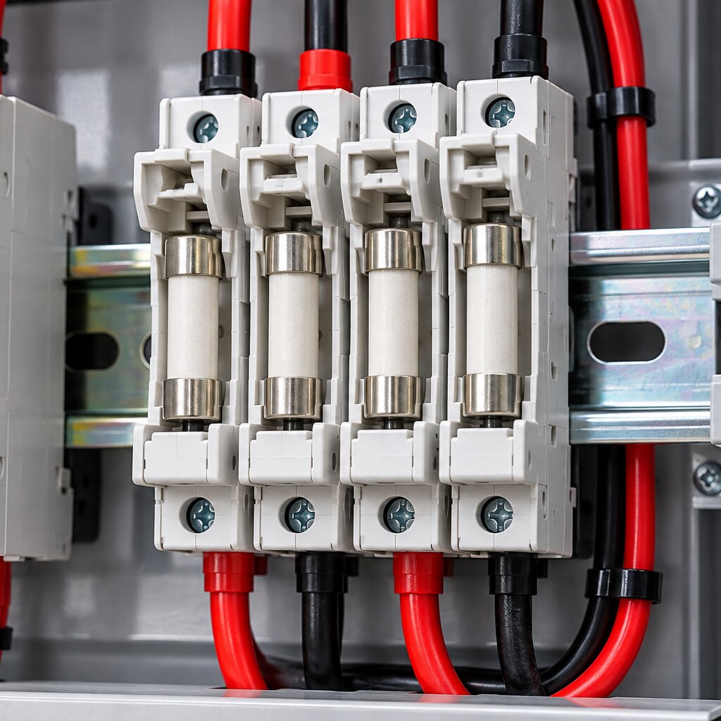
The fuse base does not detect overcurrent; it holds the replaceable fuse and connects it in series with the PV conductor. Its terminals and clips must maintain low-resistance contact. Inadequate conductor insertion, wrong crimp or ferrule dimensions, incorrect torque, contamination, or loose clips create contact resistance and localized heating.
That heat can damage the fuse base while the melting element remains intact.
Install conductors within the base manufacturer’s specified range, using its stripping method, terminal torque, and retermination procedure. A fuse base is not automatically a load-break disconnect. De-energize the PV circuit with an appropriate disconnect before withdrawing a fuse; a touch-safe housing does not prevent a dangerous DC arc under load.
A replacement must retain the required gPV rating, DC voltage, interrupting rating, physical size, contact arrangement, and temperature performance.
Where the Fuse Belongs in a PV Array
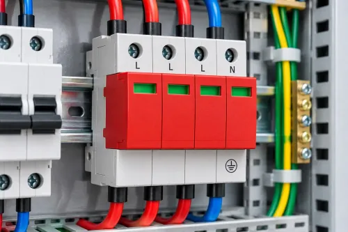
Place each string fuse in series with a PV conductor, normally where the string enters the combiner box. A series connection forces the string current through the fuse; placing a fuse across positive and negative conductors creates a fault path instead of protection.
String fusing primarily limits reverse current. One PV string normally cannot drive substantial reverse current into itself, but parallel strings can feed a faulted string through shared conductors.
A parallel-string array requires string protection when the possible reverse current from the remaining strings could exceed the module or string maximum-series-fuse rating, conductor capacity, or equipment withstand.
The module datasheet’s maximum series fuse value is an upper limit, not an automatic fuse size. Check the installation’s conductor ampacity, operating current, DC voltage, temperature conditions, and prospective fault current at the fuse location.
In a combiner box, that fault current can include contributions from several strings and connected array sections, not only one module’s Isc.
Before choosing the placement, confirm:
- Install the fuse in the positive or negative conductor required by the system grounding arrangement and local rules; ungrounded systems may require protection in both conductors.
- Put string fuses where each string can be isolated and identified, commonly inside the combiner box.
- Compare the possible reverse current from all parallel strings with the module’s maximum-series-fuse rating.
- Confirm the fuse’s DC interrupting rating exceeds prospective fault current at its actual location.
- Follow the fuse-base manufacturer’s conductor, stripping, and terminal-torque instructions.
How to Select the Fuse Rating and Breaking Capacity
Choose the fuse from the array’s worst-case voltage and current, not from its nominal label. A gPV fuse complying with IEC 60269-6 must have a DC voltage rating at least equal to the maximum system voltage, calculated from the array’s open-circuit voltage after cold-temperature Voc correction.
A “1,000 V” fuse is unsuitable if the corrected array voltage exceeds its rating.
- Confirm the fuse is gPV, not an AC-only or general low-voltage fuse. This classification covers PV overload and short-circuit interruption.
- Determine the highest continuous circuit current, including the installation’s temperature correction. Select a fuse that carries this current without nuisance operation, while remaining within the conductor ampacity and the module datasheet’s maximum series fuse limit.
- Treat the module’s maximum series fuse value as an upper limit, not the required size. Compare operating current, conductor rating, temperature performance, and coordination with the other protective devices.
- Calculate prospective short-circuit current at the fuse location. In a combiner, parallel strings and connected array sections can feed a fault, so one module’s Isc is not enough.
- Verify the fuse’s DC interrupting rating exceeds that prospective fault current at the stated maximum system voltage. DC has no natural current zero, so an AC fuse that fits the holder can fail to extinguish the arc.
- Check the selected fuse against the adopted installation rules and the manufacturer’s voltage, current, derating, and replacement instructions. The same ampere marking alone proves nothing.
How to Match the Fuse to Its Base Safely
A PV fuse is safe only when its fuse holder matches the fuse mechanically, electrically, thermally, and at the installation terminals. Matching amperes alone does not establish fuse holder compatibility.
| Dimension | What must match | Failure if ignored |
|---|---|---|
| Mechanical | Fuse body length, diameter, blade or ferrule form, physical size, and terminal arrangement | The fuse may not seat fully, or clips may contact only at their edges |
| Electrical | gPV or equivalent PV rating, DC voltage, interrupt rating, and the holder’s certified voltage rating | An AC-only fuse or 1,000 V base in a 1,500 V circuit can fail to interrupt the DC arc |
| Thermal | Continuous current, enclosure ambient temperature, adjacent loaded poles, and holder derating curve | Contact resistance raises terminal temperature and can damage the base |
| Installation | Conductor range, stripping length, ferrule or crimp method, terminal torque, and retermination instructions | A loose or over-tightened connection creates a hot spot even when the fuse element operates correctly |
Check the holder marking and manufacturer data sheet, not just the fuse label. The complete assembly must provide the required creepage, clearance, insulation, and temperature performance.
Before fitting it, confirm these points:
- Use the specified conductor size and ferrule, then apply the stated torque with a calibrated tool.
- Apply holder derating for enclosure heat, grouped poles, and poor ventilation; do not use the printed ampere value automatically.
- De-energize the circuit unless the holder is specifically listed for load-break switching.
Yueqing Growmore Electric Co can provide the dimensional drawing and derating information needed to compare a proposed fuse with its base.
Related product
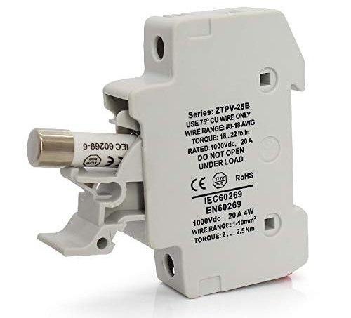 | Solar Accessories Yueqing Growmore Electric Co., Ltd. - Reliable DC Fuses & Fuse Bases for Safe Electrical Protection Company Overview Yueqing Growmore Electric Co.,... View product → |
How to Verify Protection Before Energizing the Circuit
The final check is a documented walk-through showing that the fuse, base, conductors, grounding arrangement, and isolation procedure meet the adopted installation rules, including IEC 62548 or NEC 690.9 where applicable.
1. Confirm the fuse is a photovoltaic gPV device with a DC voltage rating at least equal to the cold-corrected maximum array open-circuit voltage. Check that its interrupting rating exceeds the prospective short-circuit current at the fuse location, including contributions from parallel strings.
2. Compare the installed fuse with the conductor ampacity, continuous operating current, module maximum-series-fuse limit, temperature correction, and equipment listing. The module limit is an upper boundary, not automatic proof that the selected fuse is correct.
3. Inspect the base for the exact fuse dimensions, voltage and current ratings, terminal markings, enclosure suitability, and torque values. Verify conductor size, insulation rating, polarity, secure terminations, and the absence of damaged or overheated parts.
4. Verify the grounding arrangement against the design drawings and adopted code. For an ungrounded or functionally grounded array, confirm whether one or both conductors require overcurrent protection; a fuse on one conductor is not universally sufficient.
5. Prove that the replacement procedure starts with an approved disconnect. A fuse base is not automatically a load-break disconnect; use a load-break disconnect before withdrawing a fuse unless the holder is specifically marked and listed for interruption under load. Record the replacement fuse type and rating so nobody substitutes an ordinary AC fuse.
Frequently asked questions
How does a DC fuse stop a solar circuit fault?
Excessive current heats the fuse element until it melts and opens the DC circuit. The fuse must have a DC voltage rating and breaking capacity high enough for the fault current.
Where does a fuse belong in a PV array?
Install overcurrent protection in the required string conductors before parallel strings combine, following the array design and equipment manufacturer’s instructions. Do not place a fuse where it cannot interrupt current from every connected source.
How do you select a solar DC fuse rating and breaking capacity?
Check the PV module short-circuit current, design current, maximum system voltage, temperature correction, and the array’s prospective fault current. Choose a photovoltaic fuse with a voltage rating at least equal to the system voltage and a breaking capacity above the available fault current.
How do you match a PV fuse to its fuse base?
Confirm the fuse size, contact configuration, rated voltage, DC category, polarity marking, conductor range, and manufacturer compatibility. Use a base designed for photovoltaic DC service rather than a similar-looking AC holder.
What should you verify before energizing a solar DC circuit?
Check fuse and base ratings, polarity, conductor termination torque, insulation condition, continuity, string voltage, and isolation between conductors and earth. Install the fuse only after confirming the circuit is de-energized and correctly identified.