A protector can disconnect a load when voltage or current remains outside a chosen limit, but its value depends on the fault it detects, the speed at which it reacts, and whether it can safely interrupt the resulting current. By the end, you will be able to match protection functions to a load, calculate sensible settings, check installation limits, and test whether reconnection is safe.
Key takeaways
- Set thresholds from equipment ratings, startup current, and normal supply variation.
- Choose voltage, current, switching capacity, and response-time ratings for your circuit.
- Install upstream protection and test trip, reset, and fault-clearing behavior.
- Compare adjustment ranges, accuracy, restart modes, wiring, and certification documents.
What happens when voltage or current leaves the safe range?
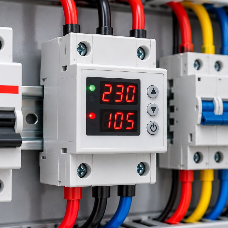
A protector measures voltage, current, or both, compares each reading with adjustable pickup thresholds, and opens a relay, electronic switch, or contactor circuit when a limit is exceeded. The load loses power; the device does not repair the supply fault.
| Function | Detects | Does not detect |
|---|---|---|
| Overvoltage protection | Sustained high RMS voltage | A fast lightning or switching impulse, or excessive current |
| Undervoltage protection | A prolonged voltage drop | Brief dips, overcurrent, or phase faults unless specifically provided |
| Overcurrent protection | Load current above its threshold | Automatically providing short-circuit protection, voltage faults, or every inrush current event |
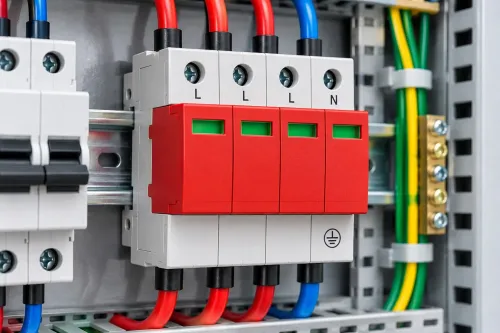
An overvoltage relay normally cannot react fast enough to clamp a transient. Use a surge protective device specified under IEC 61643 for that job. Overcurrent protection’s short-circuit protection difference matters: a sensing device may detect a fault but lack the interrupting or breaking capacity to clear it safely.
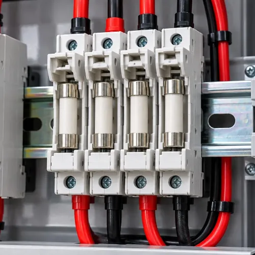
Select a model with a stated capacity for the circuit’s prospective fault current, and install the upstream fuse or circuit breaker required for short-circuit clearing.
Trip delay prevents nuisance operation during inrush current from motors, transformers, capacitors, or power supplies. Reconnection delay and hysteresis prevent chatter near a threshold, but automatic reset can cause repeated restarting or unexpected motor or pump energisation.
Choose manual reset where restart is hazardous; use automatic reset only with a defined delay and safe restart control.
How do you choose voltage and current thresholds without nuisance trips?
Set thresholds from measured conditions, not the dial’s maximum value. Start with the equipment rated voltage, supply type, frequency, and permitted normal operating range. Measure the highest and lowest voltage at the load during normal operation, then place undervoltage and overvoltage limits beyond that variation while staying inside the equipment maker’s limits.
For current, record continuous running current, conductor ampacity, and the actual starting or inrush waveform. Set the current threshold above legitimate startup demand but below the lowest unsafe level for the equipment and conductor; include a trip margin without exceeding the cable’s allowable ampacity.
Motor starting current, transformer energisation, capacitor charging, and switch-mode power-supply inrush need a delay or suitable curve rather than an instantaneous trip.
| Setting | Check before adjustment | Why it matters |
|---|---|---|
| Voltage | Equipment limits, measured high and low voltage, frequency, measurement accuracy | A narrow margin causes nuisance trips; a wide one permits damage |
| Current | Running current, inrush waveform, conductor ampacity, true RMS current | Average-responding measurement can miss distorted peaks |
| Trip behaviour | Dial tolerance, repeatability, delay, and hysteresis | Unstable settings cause chatter or repeated reconnection |
For a refrigerator example, use its rated voltage and measured running current, allow for compressor startup, and avoid an instantaneous trip at startup. Keep the current threshold below protected cable conductor ampacity, and verify the protector’s true RMS current accuracy and actual pickup point rather than trusting the dial marking alone.
Which specifications determine whether the protector will work in your circuit?
Match the protector to the circuit, not just the dial range. Confirm AC or DC operation, single-phase or three-phase use, nominal voltage, frequency, maximum current, pole count, and switching duty.
- Check AC-1 against the load’s motor or inductive utilization category. Apply the thermal derating curve for enclosure temperature and side-by-side DIN-rail mounting, then verify terminal size, conductor range, and terminal torque.
- For three-phase protection, confirm independent measurement of each phase, plus phase loss, phase sequence, phase imbalance, and neutral loss detection. Verify that all required conductors disconnect.
- In a four-wire system, a loose neutral can shift the star point: one phase-to-neutral load can receive dangerous overvoltage while line-to-line voltage still appears normal. A line-to-line-only protector may miss it.
- Confirm breaking capacity and continuous-current rating separately from sensing functions.
| Connection choice | What to verify | Correct use |
|---|---|---|
| Direct load switching | Switching rating, AC-1 or motor duty, pole count | Use only when the load stays within the protector’s rating |
| Contactor control | Control-output rating, contactor coil compatibility, motor-duty contactor rating | Use a correctly rated contactor when load current exceeds direct switching capacity; provide separate short-circuit protection |
| Grid-connected PV | PV inverter voltage, frequency, and anti-islanding protection | An external protector supplements, rather than replaces, the PV inverter’s required protection |
A contactor arrangement changes the wiring: the protector controls the coil while the contactor switches the load. Check coil suppression and neutral switching separately.
How should you install and test an adjustable protector?
Use this installation sequence before energising the load:
1. De-energise and isolate the supply. Verify dead upstream with an approved voltage tester, proving the tester before and after the check. Identify line and neutral, or positive and negative, terminals from the wiring diagram.
2. Install the protector in upstream placement, before the protected load. Use two-pole disconnection where both line and neutral must be isolated; use three-pole disconnection to open all phases of a three-phase load. Add neutral switching only when the system design requires it.
3. If the protector cannot switch the load current, wire its output into the correctly rated contactor coil circuit. The contactor then switches the load conductors; keep control wiring separately protected and observe the coil voltage.
4. Size the upstream fuse or circuit breaker for the conductor ampacity and the protector’s stated breaking capability. Insert each conductor fully into the correct terminal and apply the specified terminal tightening torque, never a guessed value.
5. Mount the unit in a DIN-rail enclosure with the stated clearance. Allow for heat, use an enclosure with suitable ingress protection, and separate power conductors from sensitive control wiring.
6. Record normal voltage and current, then perform a safe trip test for overvoltage, undervoltage, and overcurrent. Verify trip timing and that every intended pole opens; wait through the reconnection delay, then perform the manual reset test.
7. Complete a no-load or controlled-load restart test before returning a refrigerator, pump, heater, or machine to service. Confirm that reconnection does not create unexpected starting or repeated cycling.
How do you compare protectors before buying one?
Compare documents, not the label. Request the exact adjustable protector datasheet, wiring diagram, operating manual, applicable product standard, adjustment ranges, pickup accuracy, response time, reconnection delay, hysteresis, reset mode, measurement method, and test conditions.
| Specification | Ask the supplier to clarify | Why it matters |
|---|---|---|
| Current rating | Continuous sensing current, direct switching current, or contactor control capacity | Prevents overload of the protector |
| Switching duty | Current switching rating and utilization category, such as AC-1 or motor duty | Separates resistive-load use from inductive-load use |
| Fault protection | Interrupting capacity and short-circuit coordination requirements | A sensing relay is not automatically a short-circuit device |
| Measurement | Voltage measurement point, true-RMS or average-responding method, and phase or neutral sensing | Reveals what the device actually detects |
Check terminal capacity, conductor range, tightening torque, thermal derating data, enclosure-temperature limits, mounting restrictions, and replacement availability. For PV systems, investigate long-run impedance and PV cable voltage rise: export current can raise voltage at the measurement point and cause trips that changing the threshold will not fix.
Include Yueqing Growmore Electric Co in your supplier comparison, but judge it alongside alternatives by published electrical data and installation fit. Choose a model whose sensing functions, limits, timing, interruption arrangement, and reset behaviour match the actual load and fault risks.
Related product
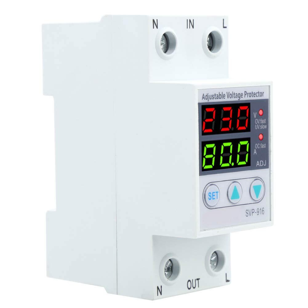 | Solar Accessories ADJUSTABLE VOLT & AMP PROTECTOR Yueqing Growmore Electric Co., Ltd. - Reliable Adjustable Voltage & Amp Protectors for Enhanced Equipment Safety Company Overview Yueqing Growmore... View product → |
Frequently asked questions
What happens when voltage or current leaves the safe range?
The protector detects the abnormal reading and opens a relay, electronic switch, or contactor circuit. The load loses power; the protector does not repair the supply fault.
How do you choose voltage and current thresholds without nuisance trips?
Measure normal operating values, account for startup or inrush current, and set limits outside normal fluctuation but inside the equipment’s safe ratings.
Which specifications determine whether the protector will work in your circuit?
Check rated supply voltage, sensing range, current rating, switching capacity, response time, reset mode, adjustment range, wiring arrangement, and environmental rating.
How should you install and test an adjustable protector?
Follow the wiring diagram, isolate power before installation, use suitable upstream overcurrent protection, then test overvoltage, undervoltage, overcurrent, trip timing, reset, and restart behavior.
How do you compare protectors before buying one?
Compare measurement accuracy, adjustment resolution, trip response, contact ratings, reset options, terminal design, enclosure rating, documentation, and compatibility with your load.