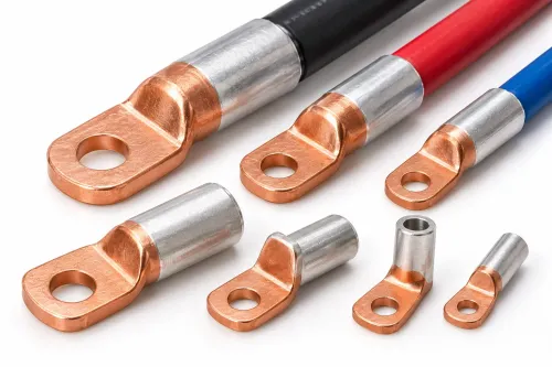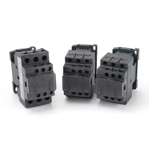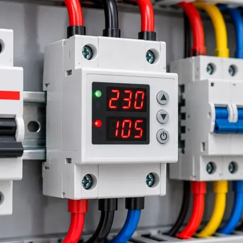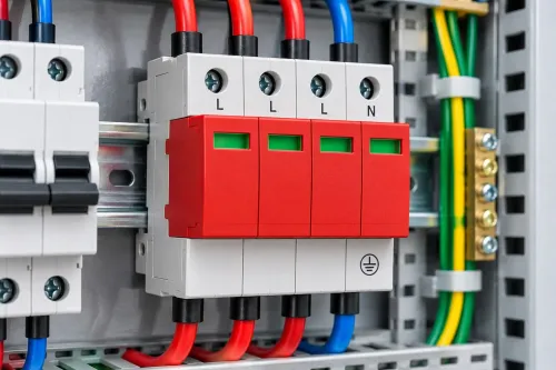
A solar array needs more than modules and an inverter: the wrong fuse, connector, isolator, cable gland, or surge device can create heating, arcing, water ingress, or an unsafe shutdown. By the end, you will be able to map accessories to each installation zone, check their ratings and compatibility, and complete a practical pre-energisation inspection.
Key takeaways
- Use IEC 62930 or EN 50618 H1Z2Z2-K PV cable outdoors.
- Match DC fuses, SPDs, and isolators to system voltage and fault current.
- Inspect connectors, cable routing, glands, and enclosures for heat and water ingress.
- Record torque values, test results, labels, and replacement intervals at commissioning.
Build the accessory checklist by installation location
Start the solar installation checklist by assigning each accessory to its exposure and electrical function. A rooftop component faces ultraviolet light, rain, heat, and mechanical movement; an indoor component faces different risks. Select PV cable certified to IEC 62930 or EN 50618 H1Z2Z2-K, not generic outdoor building wire.
| Location | Accessories | Purpose |
|---|---|---|
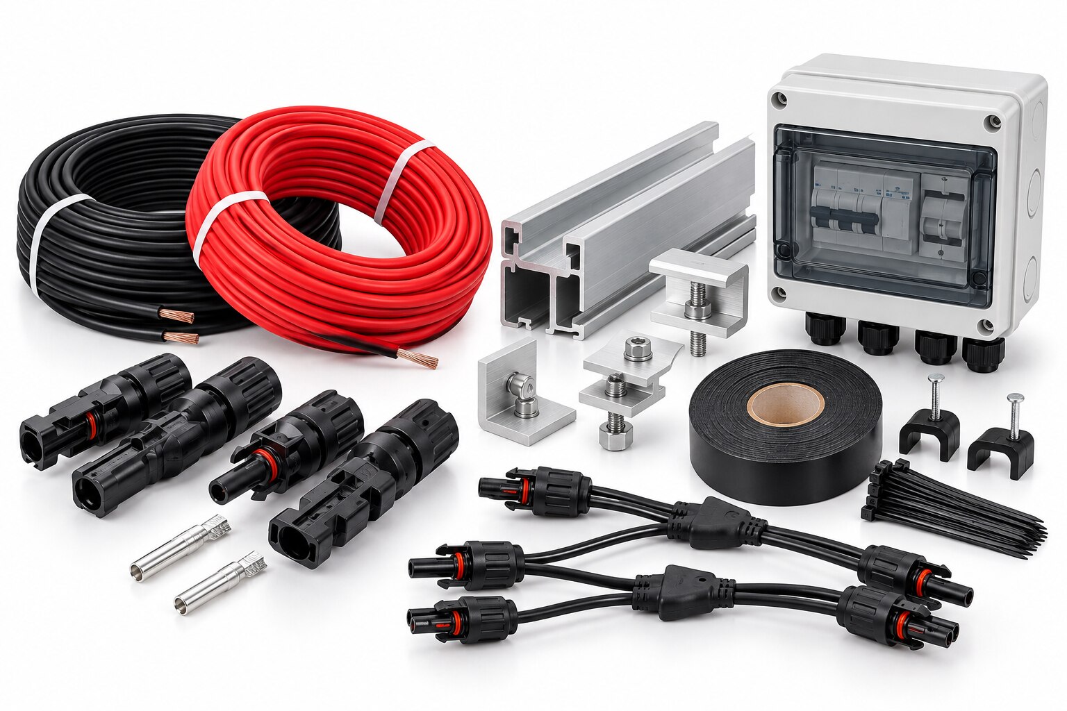
| Roof | PV cable, MC4 connectors, junction box, UV-stable clips, grounding conductors | Connect modules, support cables, seal transitions, and bond exposed metalwork |
| Combiner box | gPV fuses and fuse bases, DC SPD, DC isolator, junction terminals, cable glands | Protect parallel strings, limit surge damage, provide isolation, and contain terminations |
| Inverter | DC isolator, DC SPD where specified, grounding conductor, monitoring communications | Switch the array safely, coordinate surge protection, and transmit operating data |
| AC side | AC isolator, AC SPD, circuit breaker, residual-current protection where required, AC cable, monitoring meter | Disconnect the inverter, protect the building circuit, and measure exported or consumed energy |
- Keep connectors off the roof surface and prevent unsupported cable weight from pulling on contacts. Use clips, trays, or ties rated for rooftop UV and temperature.
- Check cable glands against IEC 60529 IP rating standards. Match the gland sealing insert to the cable diameter, fit the locknut, and close every unused entry with a suitable blanking plug.
- Confirm the enclosure material, UV resistance, corrosion protection, and temperature rating separately; an IP rating alone does not prove rooftop suitability.
Size and select DC fuses, SPDs, and isolators correctly
Calculate the array’s maximum open-circuit voltage at the lowest expected temperature, then choose every DC device above that value. The DC isolator must carry the array’s operating current and interrupt it under photovoltaic DC conditions; select a device covered by IEC 60947-3 with the correct DC-PV utilization category, pole arrangement, polarity, and load-breaking duty.
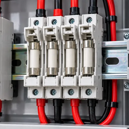
Size string fuses from string short-circuit current, temperature correction, the module’s maximum series-fuse rating, and the number of parallel strings. More parallel strings increase possible reverse current, but a small array does not automatically need a fuse in every string.
Use string fuses that are gPV fuses IEC 60269-6, installed in fuse bases with matching voltage and current ratings, touch-safe construction, and an enclosure-compatible pole arrangement.
| DC SPD choice | What it withstands | When it applies |
|---|---|---|
| Type 2 | Induced and switching surges | Standard PV-side surge protection where no direct lightning-current path is expected |
| Type 1 | Partial lightning current | An external lightning-protection system or risk assessment requiring lightning-current protection |
| Type 1+2 | Lightning current and induced surges | Coordinated protection where both duties apply |
Select a DC SPD IEC 61643-31 with a Ucpv rating above the cold-weather maximum open-circuit voltage; an AC SPD is not a substitute. Coordinate its earthing conductor, discharge path, and residual voltage with the building’s lightning-protection and earthing system. Verify polarity, continuity, insulation resistance, operating voltage and current, and isolator operation before energising.
Prevent connector, cable, and enclosure failures
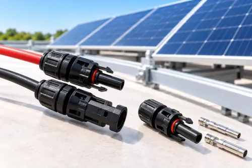
Treat MC4 compatibility as a connector-system question, not a shape comparison. Use mating halves from the same manufacturer and approved series, confirm IEC 62852 documentation, and reject visually similar “MC4-style” parts with no traceable approval. A connector that clicks together can still have poor contact pressure and overheat.
Install every connector with the specified strip length, contact, crimp tool, and die. Check the crimp profile and contact diameter against the manufacturer’s drawing; a loose crimp creates resistance heating, while an over-crimped contact can crack or deform. Support the cable separately so its weight never pulls on the contact.
- Select photovoltaic cable compliant with IEC 62930 or EN 50618 H1Z2Z2-K, rated for the array’s maximum DC voltage, current, wet locations, UV, temperature, and installation method.
- Size 4 mm² and 6 mm² solar cable for current capacity and voltage drop; do not substitute generic outdoor building wire.
- Route cables in UV-stable clips, trays, or ties, away from sharp roof edges and standing water. Ordinary nylon ties can become brittle under rooftop heat and UV.
- Fit each gland with its specified cable outside diameter, sealing insert, locknut, and blanking plug. An unused entry, oversized gland, or wrong cable defeats the enclosure’s IP rating.
- Keep connector bodies suspended and fully engaged; never bury them in water or leave them hanging from terminals.
IEC 60529 IP testing does not prove UV, salt-mist, corrosion, or rooftop-temperature suitability. Check those properties separately for combiner and isolator enclosures, then verify gland tightness and cable support before energising.
Coordinate AC protection, earthing, monitoring, and shutdown
The inverter’s AC output needs a coordinated chain: an AC isolator for local disconnection, a circuit breaker for overload and short-circuit protection, residual-current protection RCD/RCCB where required by the inverter and local code, and an AC SPD at the distribution point.
Select each device for the inverter’s rated current, prospective fault current, earthing system, and neutral arrangement.
- Fit the AC isolator where the inverter can be safely disconnected for servicing. Confirm its switching capacity and pole arrangement; do not substitute a device intended only for DC or nominal-current isolation.
- Install the circuit breaker and RCD/RCCB in the correct distribution-board position. Check the inverter manual for Type A or Type B residual-current protection, because transformerless inverters can produce smooth DC residual current.
- Choose an AC SPD for the supply voltage and earthing arrangement. Use Type 1 or Type 1+2 coordination where the building has lightning protection or the risk assessment includes partial or direct lightning currents; Type 2 alone is not always adequate.
- Bond the inverter frame, mounting system, enclosures, and protective conductors to the building’s main earthing terminal. Keep the conductor route short and avoid using monitoring wiring as an earth path.
- Connect an energy meter or current transformer at the grid connection so monitoring distinguishes solar generation, building demand, and import. A communications failure must not disable protection.
- Provide rapid shutdown only where the adopted code requires it, such as NEC 690.12 for many US building-mounted systems. Test its control circuit and verify that shutdown reaches the defined boundary.
Commission, document, and maintain every accessory
Before energisation, complete the IEC 62446-1 handover tests and preserve the results with the installation records. A string voltage reading alone does not prove a safe system.
- Verify each string’s polarity, open-circuit voltage, and short-circuit or operating current against the design.
- Test protective-conductor and equipotential-bonding continuity, including rail splices, module frames, and roof attachments.
- Perform insulation-resistance testing on the DC circuits using the test voltage specified for the equipment and system design.
- Operate every DC and AC isolator, confirm protective-device operation, and check the DC SPD status indicator before closing the circuit.
- Record torque values for terminals, fuse bases, isolators, earth bars, and connector assemblies; add test instruments, dates, readings, installer identity, component part numbers, and photographs to the handover file.
Compare accessories on more than purchase cost. A traceable part with a clear replacement procedure reduces troubleshooting time, while an inaccessible fuse or an SPD without a visible status indicator increases maintenance effort.
| Accessory choice | Safety | Maintenance effort | Traceability |
|---|---|---|---|
| Listed, compatible connector and fuse system | Correct mating and fault interruption | Simple replacement | Part number and batch can be recorded |
| Generic substitute with unclear compatibility | Higher heating or interruption risk | Fault-finding takes longer | Supplier evidence may be incomplete |
| Accessible, labelled SPD and isolator assembly | Fast isolation and status inspection | Visual checks are straightforward | Labels, ratings, and service dates remain visible |
If Yueqing Growmore Electric Co is on your shortlist, request the connector compatibility list, fuse-base pole arrangement, torque guidance, and batch records before approval.
Related products
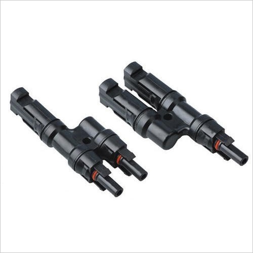 | Solar Accessories Yueqing Growmore Electric Co., Ltd. - High-Quality MC4 Connectors for Solar Power Systems Company Overview Yueqing Growmore Electric Co., Ltd. View product → |
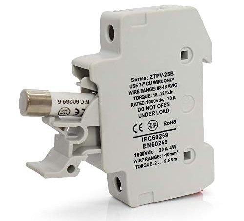 | Solar Accessories Yueqing Growmore Electric Co., Ltd. - Reliable DC Fuses & Fuse Bases for Safe Electrical Protection Company Overview Yueqing Growmore Electric Co.,... View product → |
Frequently asked questions
How do you choose solar accessories for different installation locations?
Assign each accessory to its exposure and electrical function. Rooftop parts need UV, rain, heat, and mechanical-movement resistance, while indoor parts need suitable voltage, current, enclosure, and fire-protection ratings.
How should you size DC fuses, SPDs, and isolators in a solar installation?
Check the PV array’s maximum voltage, operating current, short-circuit current, string count, and available fault current. Select DC-rated devices with ratings above the circuit demand and install them according to the equipment manufacturer’s wiring instructions.
How can you prevent solar connector, cable, and enclosure failures?
Use compatible PV connectors, IEC 62930 or EN 50618 H1Z2Z2-K cable, correct crimping tools, supported cable routes, sealed glands, and enclosures rated for the installation environment. Keep connectors out of standing water and avoid mixing connector brands unless compatibility is documented.
What must you check during solar system commissioning and maintenance?
Verify polarity, insulation resistance, continuity, protective-earth connections, torque values, labels, shutdown operation, monitoring communication, and AC and DC protection. Keep test results, device ratings, serial numbers, and inspection dates in the system records.
Related products
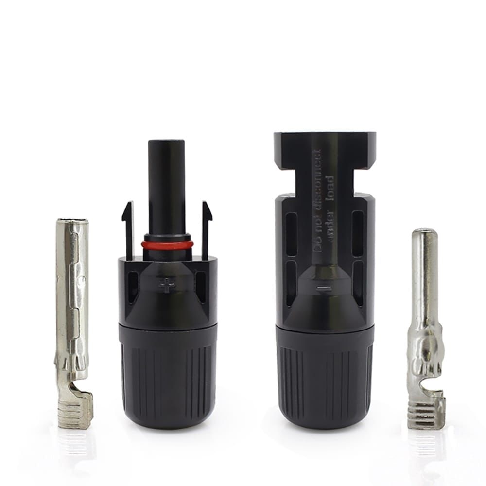 | 1000VDC SOLAR CONNECTOR ₹25 High-quality solar DC connector designed for reliable and safe photovoltaic system connections up to 1000V DC. View product → |
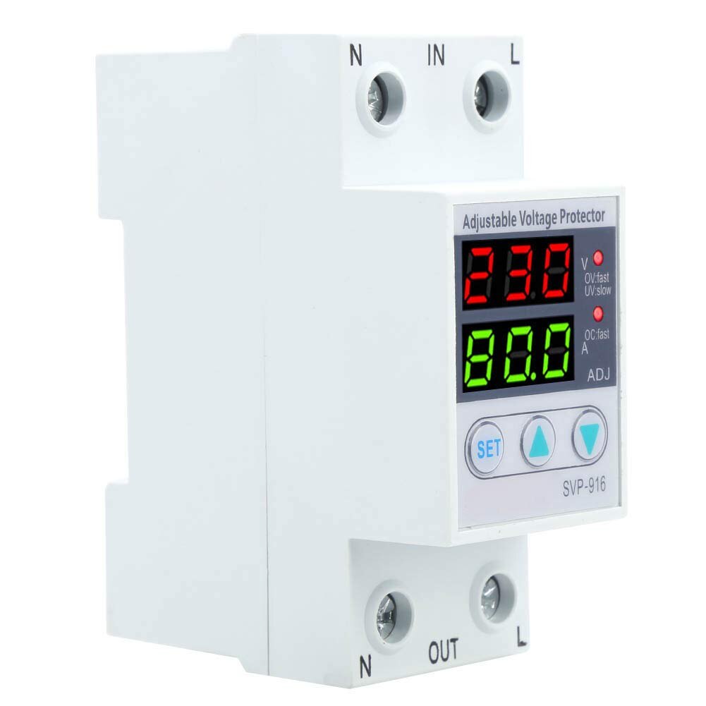 | Solar Accessories ADJUSTABLE VOLT & AMP PROTECTOR Yueqing Growmore Electric Co., Ltd. - Reliable Adjustable Voltage & Amp Protectors for Enhanced Equipment Safety Company Overview Yueqing Growmore... View product → |
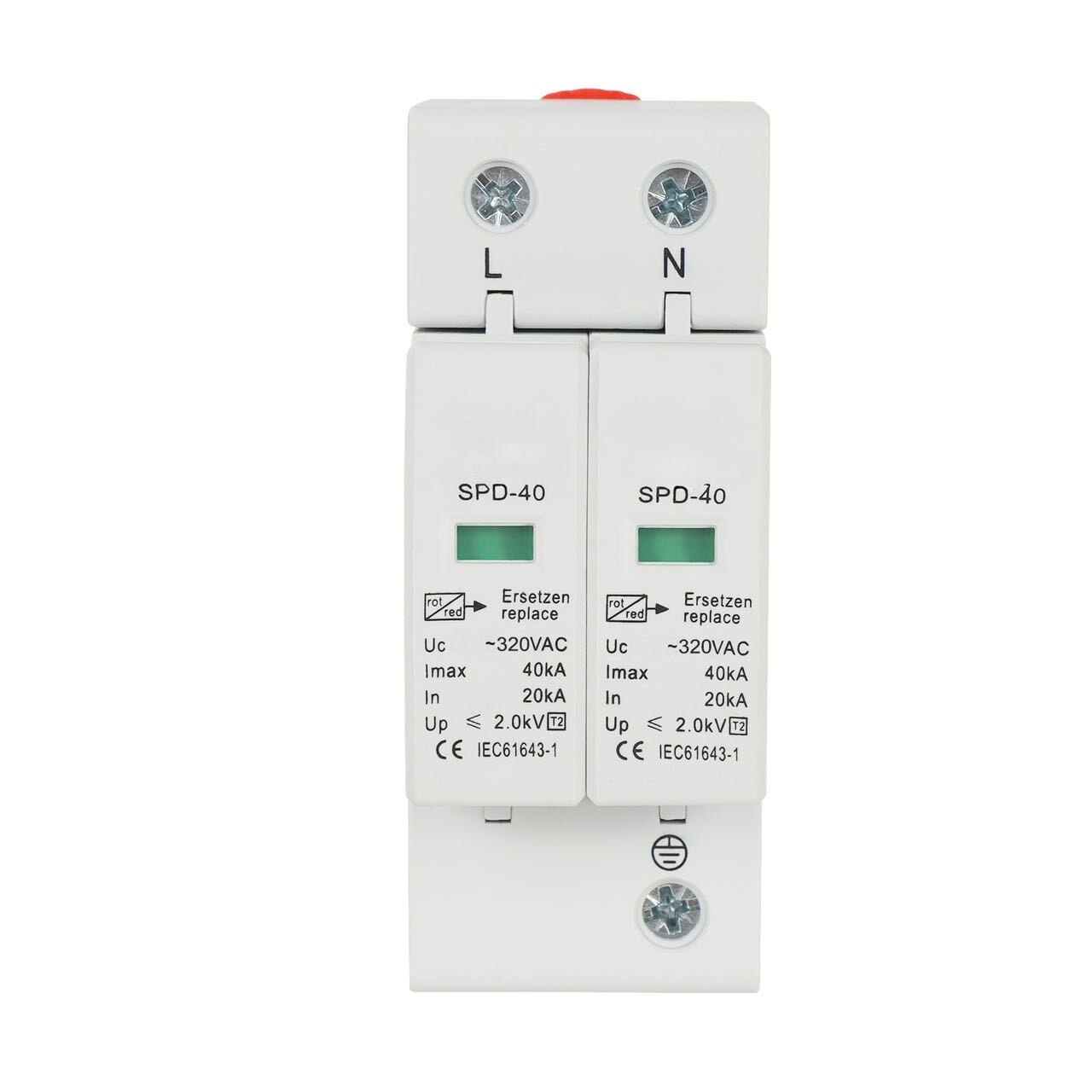 | Solar Accessories Yueqing Growmore Electric Co., Ltd. - Protect Your Electrical Systems with Advanced Surge Protection Devices (SPD) Company Overview Yueqing Growmore... View product → |