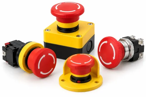
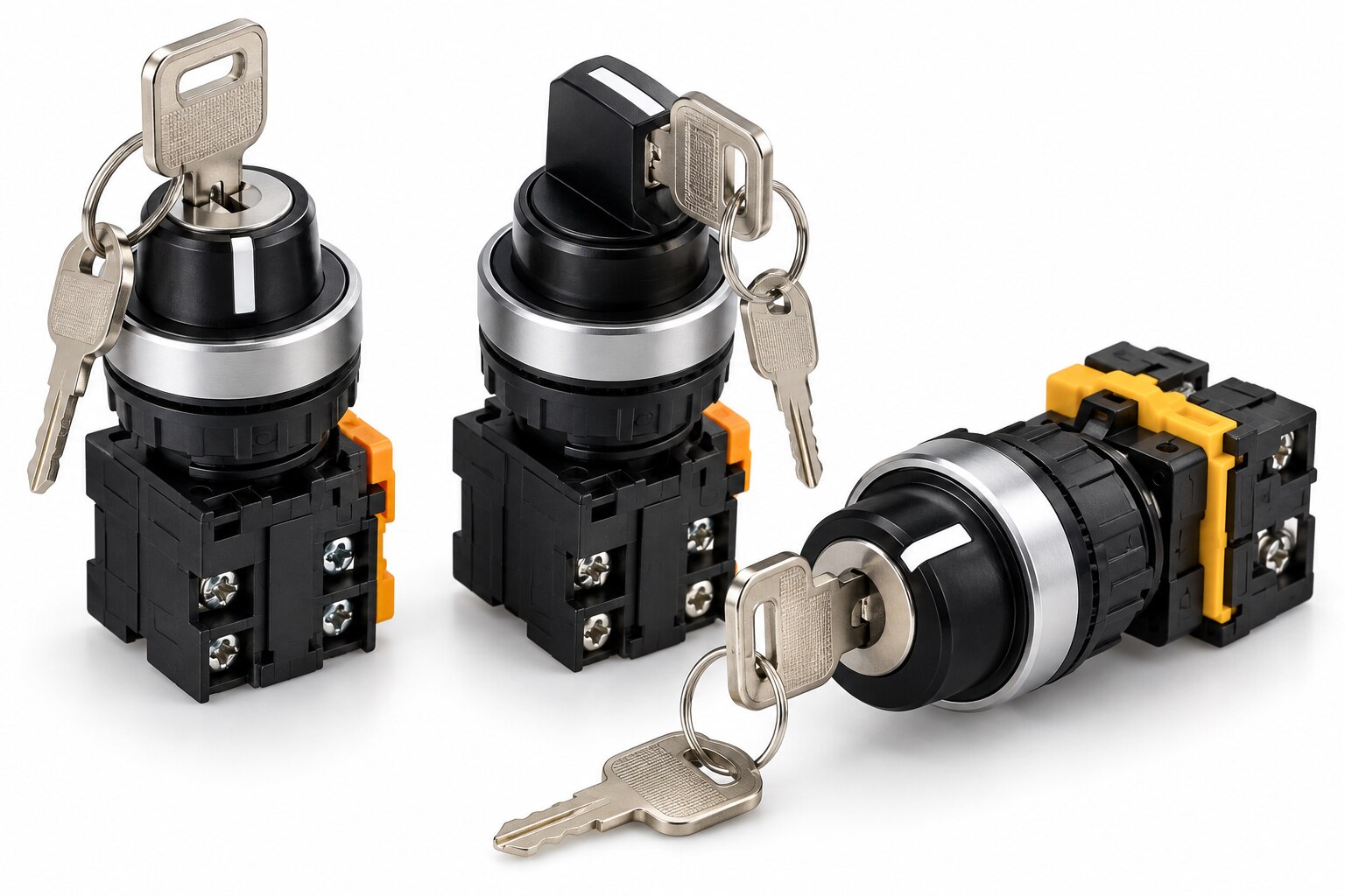
A three-position keyed switch can assign operating authority, select a machine mode, or place equipment in a defined control state, but the legend on its face does not reveal how its contacts behave. By the end, you will know where these switches fit, how key removal and spring return affect access, and which electrical and safety details to verify before specifying one.
Key takeaways
- Use three positions for authority, setup, direction, or inhibited operating states.
- Treat key removal as access control, not proof that a circuit is safe.
- Read the contact diagram and verify maintained or spring-return action before wiring.
- Specify positions, contact blocks, ratings, key removal, and environmental protection separately.
Which industrial control functions use three switch positions?
A 3 position keyed button switch selects among three operating states when an on-off command is insufficient. The arrangement may choose operating authority, a setup mode, motor direction, or an inhibited state.
| Arrangement | Typical equipment | Control function |
|---|---|---|
| Local-Off-Remote | Pumps, compressors, conveyors, building services | Local panel control, stopped or inhibited, or PLC/SCADA control |
| Hand-Off-Auto | Machine tools, packaging lines, production equipment | Manual setup, stopped, or automatic sequence |
| Forward-Off-Reverse | Motors, conveyors, mobile machinery | Forward direction, stopped, or reverse direction |
| Maintenance-Run-Production | Machine tools and material-handling equipment | Service access, normal operation, or production mode |
| Setup-Neutral-Automatic | Packaging and mobile equipment | Adjustment, neutral state, or automatic operation |
The labels do not establish the circuit behavior. The schematic must show whether the center position opens every command circuit, selects a separate permissive, or leaves one circuit energized.
A Local-Off-Remote selector can authorize a panel operator while blocking PLC, SCADA, or building-management commands, then restore remote authority without changing the motor power circuit. Define what each position authorizes, inhibits, and signals.
Specify these points before approving the design:
- State what happens if the selector changes while a run command already exists.
- Require a deliberate new command after a mode change if automatic transfer could start equipment unexpectedly.
- Treat the switch as a mode or authority input, not as a motor starter, disconnect, or emergency stop.
On mobile or lifting equipment, add hold-to-run control, reduced speed, local visibility, or a separate enabling device when the selected mode does not prove that the operator can see the hazard area.
How do key removal and spring return control operator access?
A key can block an unauthorized mode change, but it cannot make an energized machine safe. A maintained selector stays in each detented position until an operator turns it; a momentary selector uses spring return when the operator releases or turns the key back.
Spring return from Manual suits temporary setup or jogging because releasing the key ends that command. Maintained Local, Off, and Remote positions suit authority selection, where the chosen mode must remain active after the operator removes their hand.
1. Specify the key removal positions separately from the three operating positions. Ask whether the key is removable in Off only, in Off and another position, or in every position.
2. Assign the access consequence. Removing the key in Remote can leave control with a remote PLC or SCADA operator. Removing it in Off can prevent casual reactivation. Allowing withdrawal in every position can let different personnel retain ownership of the selected mode.
3. Verify the manufacturer’s actual key-removal table, not the bezel markings. The three mechanical positions do not reveal where the key can be withdrawn.
4. Test spring return, existing run commands, and control-voltage restoration during commissioning. A selector that returns from Manual can produce an unexpected loss of command; a maintained selector can preserve authority longer than intended.
5. Keep protection separate. A keyed selector does not isolate line power, discharge stored energy, or prove a guarded hazard is safe. Use a lockable disconnect and lockout/tagout procedure, then evaluate guard interlocks, hold-to-run controls, reduced-speed setup, local visibility, and separate enabling devices. Possession of a key is access control, not personnel protection.
How should you wire and read the switch contacts?
Start with the manufacturer’s contact truth table, not the position labels. Identify the common terminals for each pole, then record which normally open contacts close and which normally closed contacts open in positions 1, 0, and 2.
| Position | Record from the supplied schematic | Control meaning |
|---|---|---|
| 1 | NO contacts closed; NC contacts open | State defined by the manufacturer |
| 0 | NO contacts closed; NC contacts open | Do not assume “off” means every circuit is open |
| 2 | NO contacts closed; NC contacts open | State defined by the manufacturer |
Terminal numbers such as 11–12 and 13–14 are common conventions, not a universal guarantee. The supplied schematic controls. Check the switching angle, detents, and whether the device has one contact block or two independent blocks.
Two blocks can provide separate status and command circuits, but they do not automatically create a safety-rated redundant input. Count the circuits that can switch directly before adding interposing relays. Use one pole for a contactor-coil command, another for a PLC mode input, or separate blocks for mutually exclusive permissives when the ratings permit.
Match the contact rating to the actual load. An AC resistive rating does not establish suitability for an inductive contactor coil, solenoid, DC load, or electronic PLC input; add coil suppression where the circuit design permits. Confirm the control-voltage supply, fuse protection, polarity, and common reference.
Use an interposing relay when the selector cannot carry coil current, voltages differ, or a PLC output needs electrical separation from field wiring.
What should you specify when comparing keyed selector switches?
Specify the complete contact arrangement, not a generic “three-position keyed switch.” State whether it is maintained 1–0–2, spring return from position 1, or another exact action; show every contact state in positions 1, 0, and 2; give the pole count, independent contact blocks, and key-removal positions.
| Specification | Generic order risks | What to document |
|---|---|---|
| Function | Unexpected maintained or spring-return behaviour | Position action, operating angle, detents, and torque |
| Contacts | Wrong circuit opens or closes | NO/NC state by position, pole count, and independent blocks |
| Access | Key removal does not match authority control | Removable key positions and panel- or door-mounting method |
| Electrical fit | A resistive rating fails on an inductive load | Contact rating for AC resistive loads, contactor coils, DC circuits, solenoids, and PLC inputs |
| Installation | The assembly does not fit or survive its location | Control-voltage supply, terminal style, enclosure rating, temperature, moisture, dust, vibration, and corrosion requirements |
Check IEC 60947-5-1 for low-voltage control-circuit devices and switching elements, including utilization categories, insulation, temperature rise, and endurance. Request the datasheet, wiring diagram, dimensional drawing, and contact-life data for the exact assembly, not merely its switch family.
Yueqing Growmore Electric Co can be compared with other suppliers when you need keyed selector hardware alongside low-voltage control, indication, and protection components. Compare the documented contact arrangement and load rating, not “high quality” or a shared product title. Ensure inductive-load ratings cover the actual coil or solenoid; add suppression where the circuit design permits.
Related product
 | Push Button Switches 3-Position Keyed Button Switch YUEQING GROWMORE ELECTRIC CO., LTD. is a trusted manufacturer and exporter specializing in high-quality push button switches and low-voltage... View product → |
Where does a keyed selector stop being a safety control?
Stop treating the selector as a safety control when it only chooses operating authority or machine mode. ISO 12100 covers machinery risk assessment, IEC 60204-1 covers electrical equipment of machines, and ISO 13849-1 covers safety-related control-system design where the machine and jurisdiction require it.
| Selector use | What it provides | What it does not provide |
|---|---|---|
| Mode or authority selection | Restricts Local, Remote, Manual, or Automatic commands | A performance level or safety integrity claim |
| Off indication | Removes a control command | Safe isolation while power circuits remain energized |
| Key access | Limits casual mode changes | Personnel protection or proof of hazard visibility |
| Maintenance permission | Selects a setup or service mode | Guard interlocking, stopping, or energy isolation |
An ordinary keyed selector earns no safety rating because it has a key or two contacts. Assess the complete function: input device, safety logic, output switching, diagnostics, fault response, and defined fault exclusions. For lifting and handling equipment, add hold-to-run control, reduced speed, local visibility, or a separate enabling device when the hazard requires it.
For servicing, use a device that disconnects and isolates the relevant energy sources and locks in the isolated position. Apply the required hazardous-energy procedure, including lockout/tagout under OSHA rules in covered U.S. workplaces.
Commission the finished scheme by testing each position, key-withdrawal state, spring return, control-voltage loss and restoration, existing run commands, and failed contacts. Record the expected response before operators use the machine.
Frequently asked questions
Which industrial control functions use three switch positions?
Three-position keyed switches select operating authority, setup or maintenance mode, motor direction, or an inhibited state when two positions are insufficient.
How do key removal and spring return control operator access?
Key removal restricts who can change states, while spring return sends the selector back to a defined position when released.
How should you wire and read the switch contacts?
Use the manufacturer’s contact diagram, identify common and normally open or normally closed terminals, then test each position before energising equipment.
What should you specify when comparing keyed selector switches?
Specify position sequence, maintained or spring-return action, key-removal positions, contact arrangement, electrical ratings, ingress protection, and terminal style.
Where does a keyed selector stop being a safety control?
A keyed selector is not a safety control by itself; use a properly designed, validated safety circuit when preventing hazardous motion or access.