A suitable emergency-stop button must match the machine’s hazards, stopping method, access points, safety circuit, and panel construction—not just its red mushroom head. By the end, you will be able to define the required safety function, compare release and contact arrangements, and reject devices that fit the panel but fail the machine’s operational or electrical needs.
Key takeaways
- Use a maintained red actuator with a yellow background where provided.
- Place the actuator where a person can reach it before reaching the hazard.
- Match the release method to restart control and risk assessment requirements.
- Verify contact ratings, terminal style, enclosure space, and safety-circuit compatibility.
What makes an emergency stop different from an ordinary stop button?
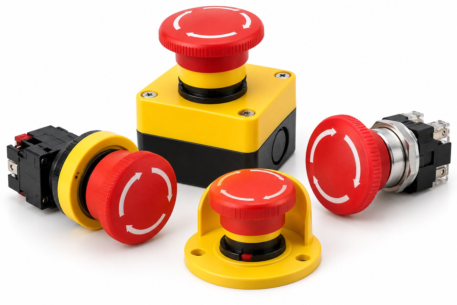
An emergency-stop device initiates an emergency-stop function; it is not simply a button that tells the machine to stop. Identify it by a red actuator, a yellow background where provided, and a maintained mechanical latch. ISO 13850 defines these visibility conventions, while IEC 60947-5-5 covers key mechanical and electrical characteristics.
- An ordinary stop push button performs a planned stop and does not necessarily remove hazardous energy.
- A momentary push button returns when released, so it can remove the initiating action while the hazard remains. It is not an equivalent substitute for a latched emergency-stop actuator.
- A selector switch selects an operating mode or permission; it is not an emergency-stop device.
- A machine isolation device disconnects energy for servicing and lockout. It is not a substitute for an emergency stop during an incident.
Define the function in the risk assessment: specify whether the machine needs stop category 0, which removes power immediately, or stop category 1, which commands a controlled stop before power removal. Stop category 2 maintains power to actuators and is not an emergency-stop solution under IEC 60204-1.
The button is only the initiating device. Assess the complete chain—wiring, safety logic, contactors or drives, and stopping behaviour—to assign the required Performance Level or SIL. Resetting must require deliberate manual action at the actuator, and reset must only permit a separate start command after the hazard is cleared.
Where should you place the actuator for the actual hazard?
Place the actuator where a person can reach it from the operator position, an intervention point, or an escape route before exposure becomes unavoidable. A button fixed only to the main panel fails this test when machine layout leaves someone near the hazard unable to reach the panel.
A hazard assessment should map reach distance, visibility, and approach paths, not just mark the nearest enclosure. Add actuators at access points or along long machinery when one device cannot cover those positions; keep each visible, unobstructed, and identifiable from the standing position.
Guarding and interlocking remain the primary controls for foreseeable access, so do not use an emergency stop as permission to leave a danger zone open.
Choose the actuator according to how people work:
- Use a prominent mushroom-style red actuator on a yellow background when operators need an immediate hand action and accidental operation is controllable.
- Add devices at transfer points, maintenance positions, and escape routes when machine layout creates separate reach zones.
- Use a shroud or recessed arrangement only when projection, clothing, tools, or passing traffic could cause accidental operation; never make the button hard to see or reach.
- Do not place it behind guarding, inside the hazard zone, or where an operator must turn away to find it.
ISO 13850 specifies the red actuator and, where a background is provided, yellow. Resetting must be deliberate at the actuator location and must not restart the machine; a separate start command remains necessary.
Which release method and safety-circuit arrangement should you specify?
Specify the release method from the reset policy and access conditions, not operator preference. A released actuator must never restart the machine; it only permits a separate manual reset after the hazard area is checked.
| Release method | Reset implication | Selection risk |
|---|---|---|
| Twist release or rotating release | The operator turns the actuator back, then uses manual reset | A protruding actuator can be released accidentally if the guard or layout allows contact |
| Pull release | The operator pulls the actuator back, then uses manual reset | Pull force and access must not allow unintended release |
| Key release | The key releases the latch, followed by manual reset | Keep the key immediately accessible during an emergency, or response time suffers |
Use normally closed contacts with positive opening action and mechanical latching; IEC 60947-5-5 defines relevant emergency-stop device characteristics. An NC label alone does not prove direct opening or resistance to a welded contact.
The complete safety function determines the required Performance Level or SIL, not the button alone. For a demanding PL or SIL, use dual-channel wiring into a safety relay or safety PLC, monitor contactor feedback, and design for broken wires, short circuits, and welded contacts.
Do not hide faults in a long series chain of ordinary buttons.
Under IEC 60204-1, choose stop category 0 when power must be removed immediately, or stop category 1 when a controlled stop must precede power removal. Neither release nor manual reset may bypass restart prevention.
How do you verify electrical ratings and panel compatibility?
Start with the contact block, not the actuator’s headline ampere number. Confirm the contact block’s AC-15 and DC-13 ratings at the actual voltage, current, switching frequency, and control load.
A rating for resistive AC does not prove that the device can switch a safety-relay input or an inductive DC load; add contact suppression where required and provide short-circuit protection for the circuit.
Use the manufacturer’s panel drawing to verify the complete mechanical interface:
- Match the panel cutout and actuator diameter, then check the permitted mounting thickness.
- Measure the mounting depth, including the contact-block stack, against the door, bezel, wiring duct, and adjacent equipment.
- Confirm the anti-rotation feature, actuator guard clearance, and operating force; a button that fits can still rotate, foul hardware, or become hard to press.
Check the environmental specification as a separate decision. An IP rating describes ingress protection, not resistance to UV exposure, oil, cleaning chemicals, impact, salt spray, or temperature extremes. For washdown or outdoor panels, demand ratings that cover the actual spray, chemical, impact, and temperature conditions rather than accepting “IP65” as a complete environmental claim.
Finally, verify that the normally closed contact has positive or direct-opening action where the safety circuit requires it. This helps open a welded contact, but the safety relay or controller still needs fault monitoring, feedback, reset logic, and suitable short-circuit protection.
What should you put on the purchase and inspection checklist?
Before production approval, demand a document pack tied to the exact part number, contact block, and revision. A catalogue page is not enough: a later substitution can change the contact arrangement or reset behavior without changing the actuator’s appearance.
- The technical datasheet must state rated voltage and current for the intended load, AC-15 or DC-13 utilization category, contact configuration, operating temperature, mechanical life, and ingress rating.
- The wiring diagram must identify normally closed direct-opening contacts, terminal numbers, channel arrangement, and any normally open auxiliary contact.
- Request direct-opening certification or test evidence against IEC 60947-5-5, plus the manufacturer’s declaration for the emergency-stop device.
- Record the reset method, such as twist, pull, or key release, and confirm that releasing the actuator cannot restart the machine.
- Check enclosure compatibility: cut-out diameter, panel thickness, mounting hardware, sealing method, and the stated IP rating after installation.
- Require installation instructions covering torque, wire size, contactor or safety-relay connection, DC suppression, inspection, and functional testing.
- Require batch traceability, including the production lot, date code, and a method for linking supplied units to the approved sample.
Document the red actuator and yellow background specified by ISO 13850. For a quoted model from Yueqing Growmore Electric Co, retain the approved wiring diagram and batch evidence with the purchase order. Reject any unit whose markings, reset method, or contact configuration differs from those records.
Related products
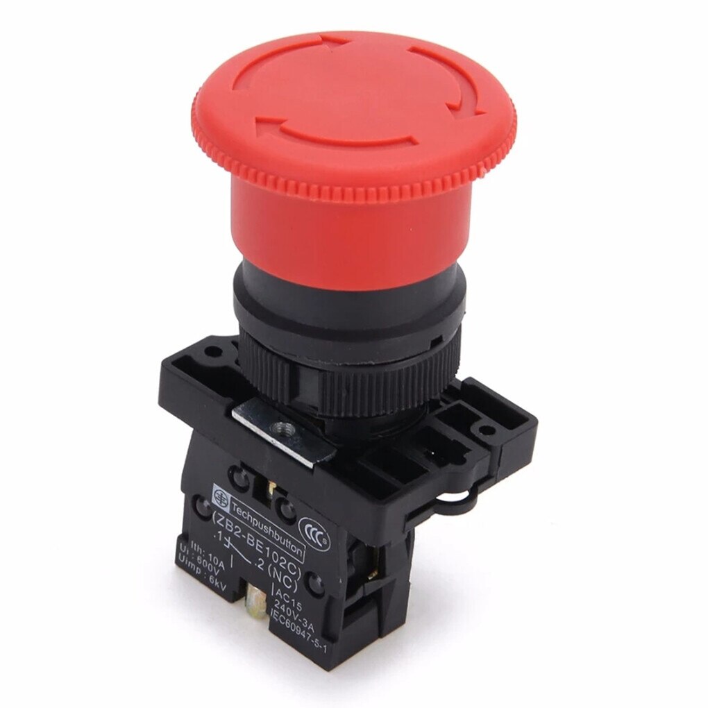 | Push Button Switches YUEQING GROWMORE ELECTRIC CO., LTD. is a trusted manufacturer and exporter specializing in high-quality push button switches and low-voltage... View product → |
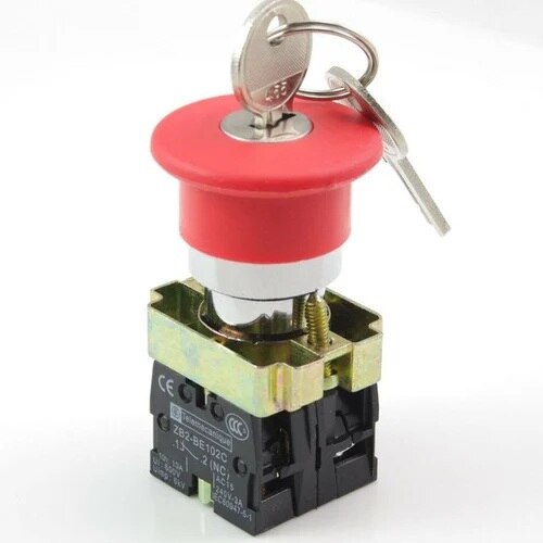 | Push Button Switches Key reset emergency Stop Button YUEQING GROWMORE ELECTRIC CO., LTD. is a trusted manufacturer and exporter specializing in high-quality push button switches and low-voltage... View product → |
Frequently asked questions
What makes an emergency stop different from an ordinary stop button?
An emergency stop initiates an emergency-stop function and uses a maintained mechanical latch. A red actuator and yellow background identify it, while ISO 13850 and IEC 60947-5-5 define key design characteristics.
Where should you place the actuator for the actual hazard?
Place it where a person can reach it quickly before encountering the hazard, with a clear view and no obstruction. Use additional actuators when one location cannot cover all access points.
Which release method and safety-circuit arrangement should you specify?
Choose twist, pull, or key release based on preventing accidental reset and controlling restart. Specify contacts and safety relays or safety controllers so releasing the actuator does not restart the machine.
How do you verify electrical ratings and panel compatibility?
Check the contact voltage, current, utilization category, short-circuit protection, terminal type, mounting-hole size, enclosure depth, and environmental rating against the panel design.
Related product
 | Push Button Switches Rotating Reset Emergency Stop Button Description YUEQING GROWMORE ELECTRIC CO., LTD. is a trusted manufacturer and exporter specializing in high-quality push button switches and... View product → |